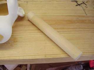
The headstick is a 1 1/4" diameter wooden dowel 9" long. Some builders prefer PVC pipe, which also works well. Both have advantages and disadvantages. Wood is easier to work with, but PVC is hollow allowing the insertion of more complex control mechanisms. This project has nothing so complex, so it uses wood.
Chapter 7 starting on page 119 of Figure Making Can Be Fun provides more information on headstick design.
Control Configuration
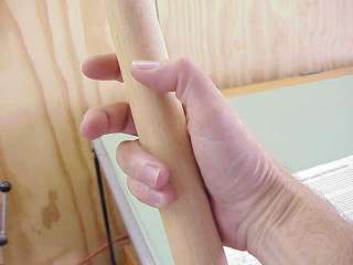
You must determine at this time how to configure the controls on the headstick. Our project uses the results of an informal survey of ventriloquists about their preferences. It assumes a right-handed ventriloquist and my hand size, which is an average male (human, of course) hand. The jaw lever is under the thumb on the left side of the headstick. The eye movement knob is at the front of the headstick about where the middle finger can operate it. The blinker lever (which you might not be installing) is above the eye control and to the right side of the headstick.
These procedures assume these control positions. Many things depend on this configuration, including the lengths of tubes, rods, and string and the placement of springs, pulleys and connections inside the head.
Determine how you want to operate your figure and where the controls will be. If possible, ask other ventriloquists to let you manipulate their figures so you can select the best configuration for your hand.
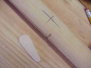
When you know which fingers are going to operate which controls, take the dowel in your hand and mark with pencil the best locations for the control levers and knobs based on the shape, length and position of your hand and fingers.
Keep in mind that hands and fingers have certain natural tendencies, and not everybody's hands are alike. On my hand, if I wiggle my middle finger up and down, my index finger tends to follow along. If your hand behaves this way and your index finger rides on the mouth control and your middle finger rides on the blinker control, you will tend to open the figure's mouth slightly whenever you blink its eyes. It takes a lot of practice to train your hand not to do that. It is better to choose a configuration that does not require this retraining, and this project reflects that choice by letting the thumb operate the jaw and the index finger operate the blinkers.
These are important decisions. Once you have determined your optimal configuration and gotten underway with the contruction, there are not many opportunities to change your mind. Get it right the first time.
The headstick hole is slightly smaller than PVC pipe. If you are building a PVC headstick, you must ream out the headstick hole in the neck.
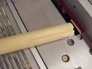
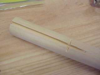
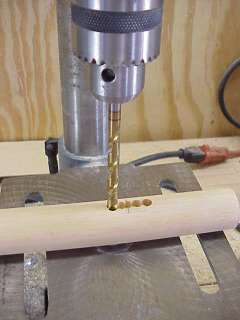
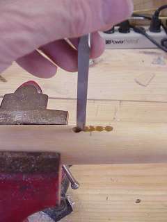
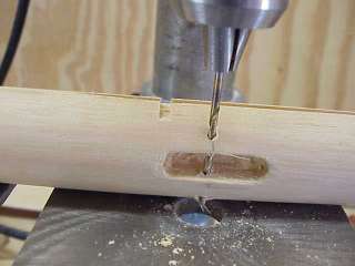
Eye Control Rod Slot
This project uses a control rod rather than a lever and strings to move the eyes from side to side. The headstick needs a slot for that rod. The rod is a brass rod that rides inside a 1/8" brass tube,
Any kind of hardwood will do as well. I cut the lever out with a scroll saw and sanded the edges smooth. One prominent figure maker makes levers from plastic toothbrush handles.
The next page has more detail on making and installing levers.
This project adds a lever for the blinkers, which you might not want to undertake at this time. The procedure is the same as for the jaw lever.