Control Levers
by Al Stevens
al@alstevens.com
This page explains how to make and install the control levers on the headstick for the mouth movement and, optionally, the blinkers.
Chapter 7
Figure Making Can Be Fun
provides more information on lever design starting on page 130.
Making the Lever
The moving mouth control lever mounts on the side of the headstick positioned under the thumb. The lever is made from 1/4" thick basswood.
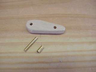
- Form the lever 1 3/4" long with one end wider than the other as shown in the following picture by using a scroll saw.
- Drill two 1/8" holes in the lever. The hole toward the narrow end is for the control string. The hole toward the thicker end is for the lever's axle.
- Cut a 3/4" length of 3/32" brass rod. Cut the rod with a hacksaw and smooth the ends with a bench grinder. This rod is the lever's axle.
- Cut a 1/4" length of 1/8" brass tube with a tube cutter.
- Open the ends of the piece with a 3/32" drill bit in the drill press, holding the tube piece with pliers.
- Ensure that the axle slides smoothly into the tube.
- Insert the tube into the hole in the lever's wide end.
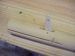
Installing the Lever
Insert the lever into the headstick slot and feed the axle through the headstick's lever holes and through the axle hole in the lever.
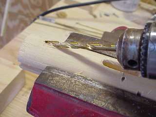
A Hole for the Control String
- Drill a 3/16" hole into the headstick for the control's string. Drill at an angle starting just below where the headstick will be visible after it is inserted in the head. Drill all the way through the top end of the dowel.
- Sand the edges of the string hole. Use a tube of sandpaper to clean out any splinters from the hole. The smoother the hole, the less wear it will exert on the string.
- If you are installing blinkers, repeat this procedure for the blinker lever.
The next page explains how to install the headstick in the head.
See Installing Mechanics for instructions on how to connect the lever controls to the mechanics inside the head.