Installing Mechanics
by Al Stevens
al@alstevens.com
This page explains how to install the mechanics in Fred's head and connect them to the linkages and controls on the headstick.
Chapter 7 in Figure Making Can Be Fun includes descriptions of many kinds of controls and mechanics.
Mouth Movement Linkage
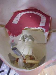
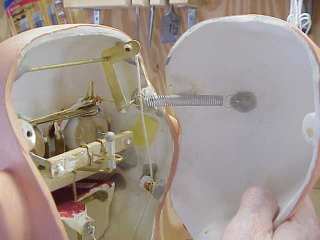
The jaw mechanism operates by a string connected to a lever on the headstick. The string feeds up through the neck, across a pulley and is attached to a screw eye on the back of the lower jaw.
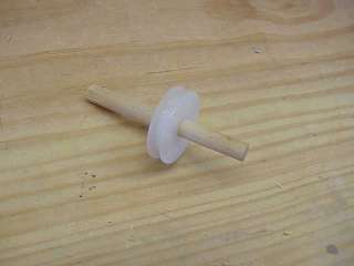
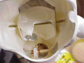
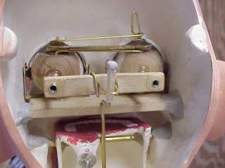
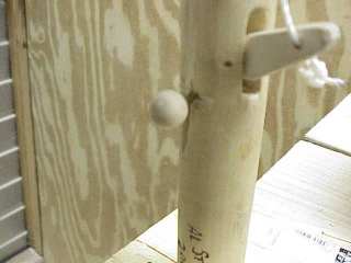
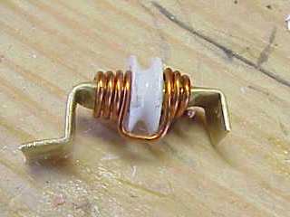
The pulley fits onto an axle as shown here. The axle is a 1/4" dowel. The pulley is the round nylon wheel from a Sliding Screen Door Roller Assembly B-551 or 11116 available at most hardware stores.
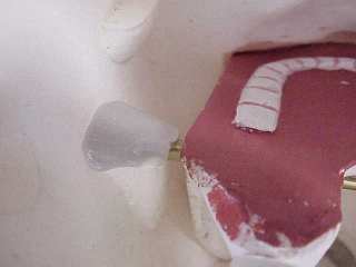
The pulley's final position is at the left end of the axle directly behind the jaw's lower screw eye.
- Cut a 3" (approximately) length of 1/4" dowel for the axle. The axle must fit horizontally inside the neck against the inner neck walls behind the jaw.
- Hand sand the axle so that the pulley turns freely when the axle is inserted through the pulley's hole.
- Drill two 1/16" holes in the axle on either side of where the pulley goes.
- Feed a loop of .18 guage copper wire through the holes and wrap them around the axle. This wire keeps the string from slipping off the axle and is also a loop for the jaw's spring to connect to.
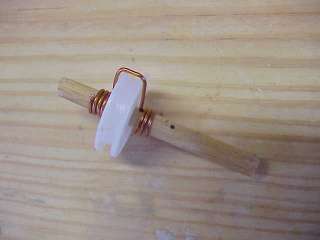
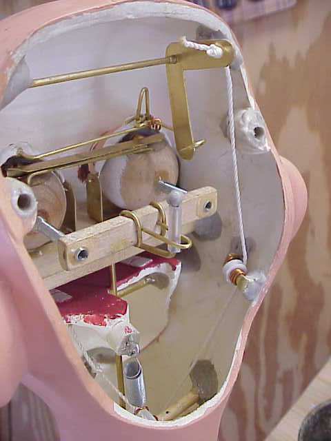
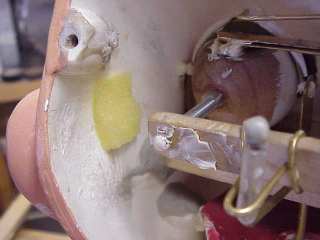
- Install the axle in the neck as shown in the next picture.
- Put the jaw in its pivot temporarily to ensure that you get the pulley lined up correctly.
- Attach the axle to the inner walls with
Apoxie Sculpt.
After completing this procedure and installing the string and spring, I learned that the string could still slip off the pulley when the head was inverted. Since the pulley mechanism was already permanently installed and these pictures were all taken (point of no return), I built up a ridge of
Apoxie Sculpt
behind the pulley on the rear inner wall of the neck to retain the string.
Preliminary Painting
Before installing the mechanics, you must do at least some preliminary painting. Read
Mixing Paint to see how to mix the paint for the project.
The inner mouth and lips must be painted before you install the jaw.
The eye rims must be painted before installing the eye assembly.
Painting the Teeth, Gums, Lips and Tongue and
Painting the Eye Rims, Eyebrows and Upper Lip explain those procedure.
Installing the Jaw
- Attach a length of nylon cord to the jaw lever that you installed on the headstick in the procecure
Installing the Lever.
Don't fasten the string permanently to the lever yet; just tie it temporarily.
- Run the cord into the inside of the head up through the hole you made in the neck in the procedure
A Hole for the Control String.
- Feed the cord through the pulley from the rear and across the top of the pulley under the copper wire retainer.
- Feed the end of the string through the screw eye that you mounted on the jaw's bottom rear ledge in the procedure
String and Spring Screw Eyes.
- Tie a knot in the end of the string to hold it in the screw eye.
- Trim the string just past the knot.
- Touch a lighted match to the trimmed end to melt the nylon and keep the string from fraying.
- Insert the jaw axle into the tube that you installed in the jaw in the procedure
Installing the Jaw Axle Tube.
- Place the two short tubes on the ends of the axle.
-
Mount the jaw in the head from the rear resting the two tubes in the slots that are cast in the head to receive them.
-
Ensure that the jaw opens and shuts freely.
- Pull the string taut at the lever and tie a knot in it so that the lever is horizontal when the mouth is closed.
- Trim the string just past the knot at the lever.
- Touch a lighted match to the trimmed end to melt the nylon and keep the string from fraying.
- Center the jaw in the jaw opening.
- Slide the two end tubes on the axle inward until they touch the ends of the long tube at the jaw.
- Use
Apoxie Sculpt to permanently bond the outer tubes to the slots on the insides of the head.
- Attach a spring from the copper wire loop on the jaw pulley to the screw eye that you mounted on the tab on the jaw's upper rear ledge in the procedure String and Spring Screw Eyes.
.
- Ensure that the mouth opens and closes freely when you manipulate the lever.
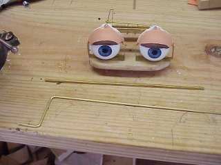
Installing the Eye Mechanism
There are two procedures to installing the eye mechanism: Installing the eye assembly that you build in the Eyes part of this document. The second procedure installs the eye movement control rod. You do these two procedures together.
- Cut a length of 1/8" brass tube.
The length of the tube depends on where on the headstick you decided to place the eye movement control on the headstick in the Control Configuration procedure. The tube reaches from just above the horizonatal slot that you cut in the headstick in the Eye Control Rod Slot procedure up the vertical slot in the same procedure, through the head, past the notches you cut in the jaw in the Notching the Jaw procedure. The tube passes through the eye assembly's platform and is flush with the top of the plaform.
For Fred, the tube is 8 1/8" long.
- Clean the ends of the tube with a 3/32" drill bit so that a 3/32" brass rod moves freely through the tube.
- Cut a length of 3/32" brass rod long enough to reach through the tube with at least one inch at the headstick end and about 3 1/2" at the other end.
- Bend the brass rod into what looks like a hand crank as shown in the next picture. The perpendicular section should be of the proper length that the upward bent end passes freely through the eye movement linkage rod on the synchronizer when everything is installed.
- Temporarily insert the eye assembly into the head on its shelves.
- Run the brass tube up through the horizontal slot in the headstick until it touches the bottom of the platform.
- Mark on the platform where the tube touched the platform.
- Remove both parts from the head.
- Drill a 1/8" hole through the platform where you made the mark.
- Feed the tube into the platform with its top end flush with the platform's upper surface.
- Insert the crank shaped brass rod into the tube from the platform end.
- Warp the eye assembly's centering springs to position the crank shape outside the synchro bar and up through the linkage rod.
- Using
Apoxie Sculpt permanently attach the eye assembly to the inside of the head. Ensure that the eyes and blinkers, if you installed them, move freely before making the final bond.
Note: You might have to build up the right shelf slightly for the platform to install precisely.
- Cut a length of nylon tube and place it on the end of the rod. This tube keeps the mechanism from clicking when you operate it.
- Put a bead of Apoxie Sculpt on the end of the rod to hold the nylon tube in place.
- At the headstick and with the eyes looking straight ahead, hold the tube and rod securely in place and bend the rod at a 90 degree angle straight out away from the headstick.
- Fill in the slot with
DAP Wood Dough or
Plastic Wood.
- Sand the slot smooth when the wood filler sets.
- Drill a 3/32" hole in a small wooden ball. (Available at craft stores where you find doll heads.)
- Impale the small wooden ball onto the eye movement control rod.
- Ensure that there the control knob has clearance to move the eyes fully from side to side.
- If not, remove the knob and whittle away some of the headstick at the horizontal slot beneath where the knob goes.
- Replace and glue the knob in place.
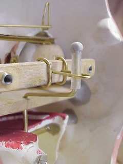
Blinker Linkage
The blinker linkage blinks the eyes when you push down the blinker lever on the headstick. The following diagram shows how the mechanism works.
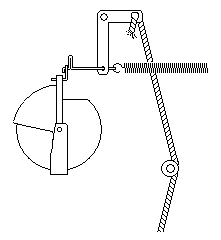 Pulling the string pulls down the horizontal leg of the L-shaped rocker. The vertical leg pushes the top of the blinkers forward, which closes the eyes. When you release the lever, the spring pulls the rocker back and opens the eyes. The small pulley keeps the string from rubbing other parts of the mechanisms.
The blinker linkage consists of a brass rod axle, a brass L-shaped rocker, a brass tube for the axle to ride in and a brass rod to connect the rocker to the linkage that you put on the blinkers in the
Shell Linkage
procedure.
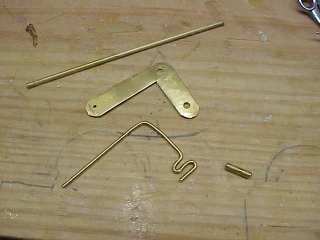
- Cut a 3 3/4" length of 3/32" brass rod.
- cut a 1/2" length of 1/8" brass tube.
- Cut a 4" length of 1/16" brass rod.
- Bend the 4" rod into the shape shown in the picture.
- Cut the rocker from an L shaped piece of sheet brass with metal shears. Make its long end 2" and its short end 1 1/4".
- Round the corners of the rocker with a bench grinder.
- Drill 1/8" holes in the rocker's short end and at its corner.
- Drill a 1/16" hole at its long end.
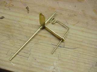
Insert the brass tube into the rocker at its corner.
Insert the axle rod into the tube.
Insert the 1/16" brass rod into the hole at the long end of the rocker.
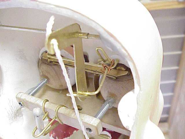
- Install the axle inside the head so that the long end of the rocker is vertical and is directly behind the rod tab in the shell linkage. Adhere the axle to the sides of the head with
Apoxie Sculpt.
- Feed the bent end of the 1/16" rod into the shell linkage rod tab.
- Fasten the 1/16" rod to the rod tab with .18 gauge copper wire.
- Bend the rocker end of the 1/16" rod into a loop to hold it in place in the rocker and to form linkage for the blinker mechanics' return spring.
- Feed a length of nylon cord through the hole at the short end of the rocker.
- Tie a knot in the cord to hold it in place.
- Burn the end of the cord so it doesn't fray.
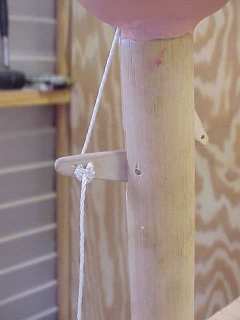
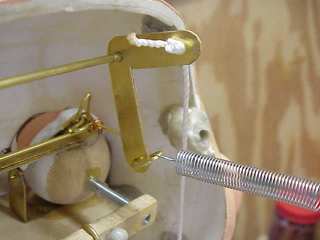
You'll have to be creative here. You need a way to keep the blinker string from rubbing against or impeding the other mechanics. The best way is to make a small pulley assembly to route the blinker string down the side of the head to the top of the headstick. I used a plastic pulley from a kit of RC airplane gears, wheels and pulleys purchased from a hobby shop. The pulley axle is a length of brass tube flattened and bent at the ends. I used .18 gauge copper wire to hold the string on the pulley.
Attach the pulley to the side of the head with
Apoxie Sculpt.
Align the pulley for the minimum twist on the string as it passes through the pulley.
If you can't make a pulley, use a screw eye. But be aware that a string pulling through a screw eye makes friction on and wears the string. Eventually the string will wear thin and possibly break.
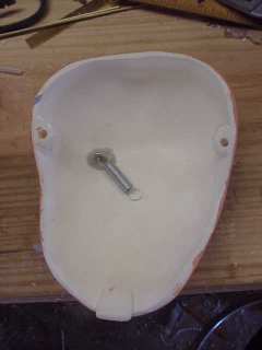
The blinker closing spring runs from the rear of the long end of the rocker to the inside of the trapdoor.
- Screw a metal screw eye into the inside of the trapdoor directly behind where the lower end of the rocker's long end will be when the trapdoor is installed.
- Reinforce the screw eye with
Apoxie Sculpt.
- Set aside a spring that runs between the screw eye and the loop in the blinker linkage.
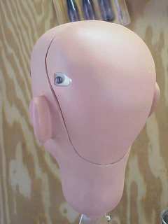
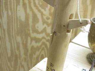
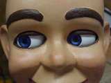
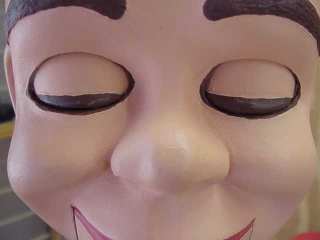
Here's Fred with his eyes closed.
Making Quiet Controls
Ventriloquist figures can be noisy as all that brass and wood rattles around inside the head. You want to minimize the mechanical noise as much as possible.
- Glue small pieces of sponge to the inside of the head where the eye movement synchro bar hits the side of the head.
- Apply
LubriMatic White Lithium Grease to every thing that moves or rubs against anything else inside the head. Squirt some on all the springs, brass fixtures, screws, washers, anywhere.
Closing the Head
- Stretch the blinker spring between the loop on the blinker linkage at the bottom of the rocker's long end and the screw eye in the trapdoor.
- Position the trapdoor in place with its lower tab inserted into the head at the neck.
- Screw the trapdoor to the back of the head.