Blinkers
by Al Stevens
al@alstevens.com
This procedure explains how to make and install shell blinkers in Fred.
Installing blinkers is one of the most daunting tasks a figure maker faces. If this is your first figure making project you might want to bypass this feature. But, if you are adventurous and you absolutely must have shell blinkers on your figure, continue with this procedure.
Page 145 in Figure Making Can Be Fun has a discussion of winkers and blinkers.
This project installs blinkers and not winkers. Winkers allow you to wink one eye independently of the other, which complicates the control linkage substantially. The initial assembly described would support that feature if you want to depart from these instructions at that time, but once you install the linkage described here, the blinkers are not able to be winkers.
Some people prefer leather blinkers. If you are one of those people, read the article
Leather Blinkers
to see if that's the way you'd rather go. If so, skip this procedure, try that one, and then go on to the next page.
This is another of those places where precision is of utmost importance. If you don't get it right, the blinkers won't work. You might even compromise the moving eye feature. But don't worry. Each of these steps is reversible. I won't tell you to do anything that can't be undone.
If there is a point of no return, it might be the procedure, Modifying the Eye Openings, where you carve the eye openings a bit wider at the top to make room for the blinkers. That's right, you're going to cut into Fred's face in this procedure. But even that intrusive operation can be undone if you are willing to resculpt the original eye openings with a casting compound.
If you're unsure about what to do and want my advice, here it is: Go for it. If you weren't the adventurous type, you wouldn't have gotten this far.
The Blinker Assembly
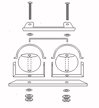
Following is a diagram showing an exploded view of the eye assembly with the initial blinker hardware added. The shells are not shown. The difference between this assembly and the one on the page describing the Synchronizer is that this assembly replaces the washers beneath the eyeballs with blinker mounting brackets and adds the blinker frames. Later you'll add blinker shells and some blinking linkage hardware.
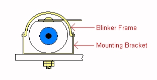
Here's a diagram of one eyeball assembly showing the mounting bracket and blinker frame. The next procedures explain how to make these parts.
Mounting Brackets
You'll make two mounting brackets. Each one is constructed from a 1/2" wide strip of sheet brass four inches long. Use a gauge that is the same thickness as one of the two brass washers the two brackets replace.
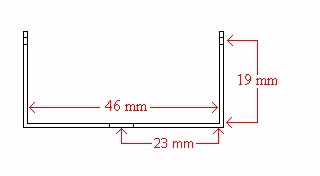
The following diagram gives the dimensions of the bracket. These must be exact in order for the blinkers to work properly. The 19 mm dimension is measured from the inside base of the bracket to the center of the blinker frame's axle hole. 46 mm is from one inside wall to the other inside wall. 23 mm is from the inside wall to the center of the eyeball's axle hole.
You must bend the 4" length of brass into the bracket shape and drill holes for the blinker frame and the eyeball axle.
- Cut a block of wood exactly 46 mm wide. Height and length are unimportant as long as the block is at least an inch high.
- Draw a line down the center of the top of the block to indicate where to drill the eyeball axle hole.
- Draw a horizontal line on each of the sides of the block exactly 19 mm up from the bottom to indicate where to drill the frame holes.
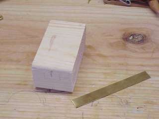
- Bend the brass strip around the wood block.
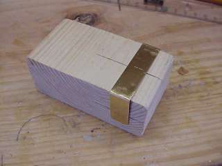
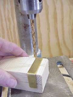
- Using the registration line on the top of the block, drill a 13/64" hole into the center of the strip for the eyeball axle hole.
Note: When drilling into sheet brass, it helps to use a nail to punch a small dent into the brass where the point of the drill bit starts. This keeps the drill bit from riding around on the smooth surface of the brass.
- Using the two registration lines on the sides of the block, drill 1/16" holes into the bracket's two walls. Center these holes in the strip.
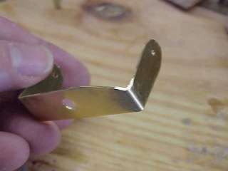
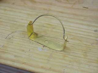
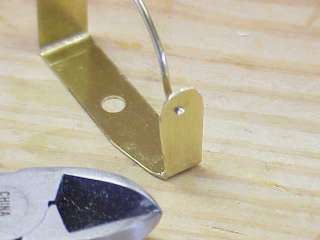
Here is one of the two brackets. Make a second one just like the this one.
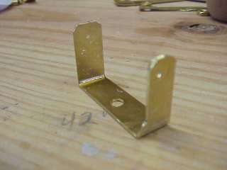
- Use metal shears to trim the front of the leg that will be on the outer side of the assembly.
- Grind this cut down with the bench grinder.
Removing this excess brass allows the assembly to fit inside the head. Note that you will still have to carve away some of the head's inside wall to make room for the assembly as explained in Carving Some Room Inside the Head.
Blinker Frames
The two blinker frames are made from 1/16" brass rods. Each frame describes a semicircle with an inside diameter of 40 mm as shown in the following diagram. The axle bends must occur on exactly the center line of the 40 mm circle.
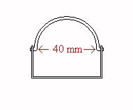
- Draw a 40 mm circle on paper with a compass.
- Draw a line through the center.
- Bend the frame carefully by hand and with small pliers using the diagram you drew as a guide until you have something that looks like the frame in the following picture.
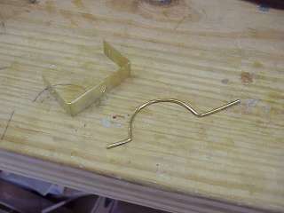
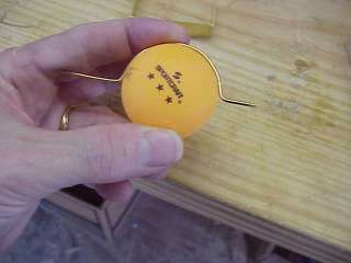
- You can use a 40 mm tournament ping pong ball as guide. But always use your compass-drawn picture to ensure that the axle bends are properly positioned.
- Trim the ends of the axles.
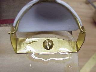
- Insert the frame into the mounting bracket's frame axle holes as shown here.
- The frame should move back and forth freely. If it does not, remove the frame and examine the axle bends to ensure that they are true.
- When the frame is properly installed in the bracket and when it moves freely without binding, trim the ends of the outer axles almost flush with the bracket.
- Disassemble the eye assembly.
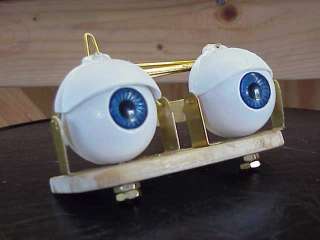
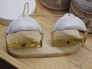
- Reassemble the eye assembly, replacing the washers beneath the eyeballs with the mounting brackets as shown here.
Blinker Shells
Now you are ready to install the shells. To make the blinker shells see the article,
Making Shell Blinkers.
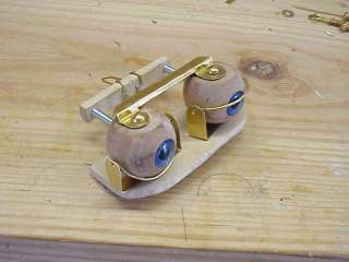
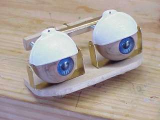
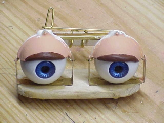
- Place the shells on the assembly with their channels over the frames as shown in the next picture. Do not glue them in place yet.
- Ensure that the shells move up and down over the eyeballs when seated with their channels in the frames.
- Ensure that the irises do not bulge out and interfere with the movement of the blinkers. If they do, you must disassemble everything and deepen the countersunk holes for the irises.
Shell Linkage
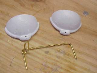
- With the shells positioned on the assembly, bend a length of 1/16" brass rod into the shape shown in the next picture. The two protuding ends must be a distance apart equal to the distance between the holes in the shells' linkage tabs when the shells are mounted on the assembly.
- Insert the linkage into the shell tabs as shown here.
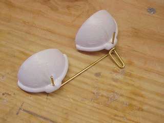
- Mount the shells on the assembly with the linkage inserted.
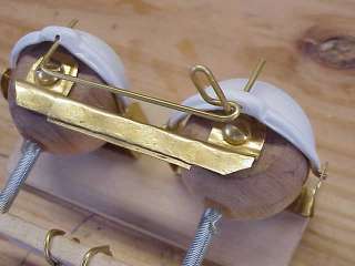
- Slide the linkage in and out of the shell tab holes until the linkage is properly aligned with the shells and the shells are at the same level with respect to the irises.
- Move the blinkers up and down to ensure that everything works smoothly. This is just a test procedure to ensure that everything works.
Gluing the Blinker Assembly
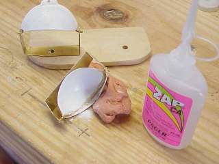
Remove the brackets and frames from the platform, the shells from the frames, and the linkage from the shells so you can glue the shells to the frames. Use
Zap
to glue the shells and frames. Don't try to use anything else. Read
Gluing Styrene
to understand why.
Gluing Shells to Frames
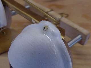
- Put a shell on its frame and ensure that it is properly positioned. Be careful here. It's easy to get the shell mounted in a slanted position. You want the front of the eyelid to be horizontal relative to the blinker assembly.
- Lower the lid until the shell is rolled down under the eyeball position (the eyeball itself is not in the assembly at this time).
- Use modelling clay as a support and position the assembly so that the curvature of the channel puts the frame axle on the upslope. Zap is runny and you don't want any getting into the axle hole.
- Sprinkle a tiny amount of baking soda into the channel.
- Gently apply a trickle of Zap into the channel.
- Wait about five seconds, turn the assembly around, and do the other half of the channel and frame.
- When the Zap sets (almost right away) use fine sandpaper to clean any residue from the inside of the shell and around the channel. This step eliminates any bumps that might interfere with the movement of the shell.
- Glue the other shell to its frame assembly the same way.
- Reassemble the eye assembly.
- Ensure that the blinkers independently travel up and down freely. If not, locate the problem area, take everything apart, and fix the problem.
Gluing the Linkage to the Shell Tabs
- With the shells installed onto the assembly, insert the ends of the frame linkage into the shell tabs.
- Get it lined up properly and ensure that the blinkers still work freely.
- Glue the shell tabs to the linkage ends with two part epoxy.
I know, I told you that stuff won't permanently stick to styrene, and it won't, but it doesn't have to. It does stick to brass, and you are just building up the brass so it doesn't slide back and forth.
- Put glue at the front of the tab where the linkage end sticks out and in the rear where it is inserted into the tab.
A hint: Suspend the assembly upside down to glue the linkage to the tabs. Epoxy glue runs all over the place, too. If the assembly is upside down, all the glue can do is drip on your workbench.
Gluing Brackets to Platform
This procedure glues the mounting brackets to the platform so that they do not rotate and alter the orientation of the blinkers.
- With the blinkers installed and working, remove the eyeballs to permanently afix the mounting brackets to the platform.
- Temporarily bolt the brackets in place.
- Place a straight edge on the platform across the back of the bracket bases
- Tighten the bolts to hold the brackets in place.
- Put a layer of epoxy glue on the brackets and the platform. Be careful not to get any epoxy on or near the bolts.
- When the epoxy sets, remove the bolts.
Painting the Eyeballs
Paint the eyeballs as described in
Painting the Eyeballs.
When the eyeballs are dry, glue the irises into their holes with Elmer's glue and reassemble the eye assembly.
Preparing the Head
By now you've tried to slide the assembly into the head, and you find that it doesn't quite fit like it did before you added the blinker assembly. In fact, it doesn't fit at all. Don't worry, you're not finished.
Carving Some Room Inside the Head
Fred's head does not have quite enough room for the eye mechanism with the blinker supports installed. You must carve some notches inside the head alongside the outer corners of the eye openings as the following picture shows. Carve these notches with an Xacto knife cutting away a little bit at a time. Insert the assembly after each carving with the blinkers fully retracted until the eyes fit flush with the eye sockets as they did before you installed the blinker assembly.
Modifying the Eye Openings
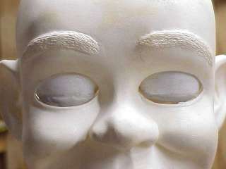
Okay, now the assembly fits but the blinkers won't close. That's because Fred comes with permanent open eyelids sculpted into his head. You have to carve them out to make room for Fred's blinkers. Examine the eye sockets from the front with the assembly in place in the head. Observe how much of Fred's permanent eyelids are in the way.
Proceed slowly carving a little at a time from around the top of the eye, trying as you go along to see how close you are and how much more you have to remove. The idea is to not carve too much and not have to put anything back. If you do make a mistake and cut away too much, replace it with
Apoxie Sculpt
and proceed more carefully after that.
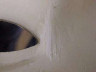
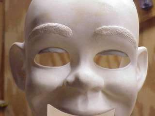
Here's Fred with one eye carved out and the other one intact. Note that the carving goes up to but not above the sculpted eyelid.

Carve so that there is minimal gap between the eyelids and the head. Allow enough gap so that the blinkers do not rub or bind when they move up and down. Carve both eyes and test the blinker operation with the eye assembly inserted in the head.
Installing blinkers this way is a retrofit because Fred's original design does not plan for them. The original eye opening is sculpted to fit a 1 1/2" ball. The blinkers are going to add diameter to the upper halves of the eyeballs, which means that the eye assembly must be moved back slightly to accommodate this additional space. As a consequence, the lower halves of the eyeballs do not fit as snugly against the lower halves of the eye openings. If you wish to compensate for this additional gap, build up the lower eye openings with Apoxie Sculpt. Unless you are doing extremely close-up work, however, this modification is unnecessary. The extra gap is not noticeable from normal performance distances.
Completing the Eye Assembly
You could stop now, but the blinkers wouldn't look realistic on Fred the way he is designed. Fred is the kind of traditional "cheeky boy" character that has noticeable dark eyeliner to highlight his eyes. When his eyes are open the eyeliner should surround the eyes. When his eyes close, the eyeliner on the lids should descend and the lids should blend into the space above the eye opening with flesh tones.
To achieve this Jerry Mahoney look, you must modify the shape of the blinkers to conform to the shape of the upper half of the eye opening and then add ridges to the blinkers.
Forming the Eyelid Edges
- Insert the eye assembly into the head.
- Lower the blinkers slightly.
- Trace with a pencil the outlines of the eye openings on the blinkers.

- Remove the eye assembly.
- Disassemble the eye assembley
- Trim the blinkers around the outlines you drew on them.
Here are the blinkers trimmed and back in the head without the eyeballs.

Adding Eyelid Ridges
- With the assembly mounted in the head and the blinkers slightly lowered, draw the outline of the ridges on the eyelids with pencil.
- Remove the assembly.
- Sculpt ridges onto the eyelids with
Apoxie Sculpt .
- Before the Apoxie Sculpt sets up, carefully insert the assembly into the head.
- Ensure that the tops of the ridges touch the tops of the eye openings at the same time when the blinkers are up.
- Ensure also that the bottoms of the ridges touch the upper cheeks together when the blinkers are down.
- Set the assembly aside and let the ridges set up.
Painting the Blinkers
Paint the eyelids and their ridges prior to permanently installing the eye assembly in the head. Read
Mixing Paint to mix the flesh tone paint for the complete project. Then read
Painting the Blinkers for instructions on painting the blinkers.
Reassemble the eye assembly with the painted blinkers installed.
Final Assembly
Using two 3/8" ignition wrenches, tighten the two nuts against one another so that the eyes move freely but there is no wobble or up and down motion of the eyeballs.